After finishing the experimental, computational and analytical phases focused on precast structures, we are now in a critical phase of the Endure project. We have finalised the design of the cast-in-place and steel/composite subassembly tests to evaluate the fuse-based segmentation concept. We are also performing preliminar tests on structural fuses and we will start the subassembly tests campaign in the coming months.
The design philosophy of structural fuses focuses on the controlled separation of specific structural elements to prevent collapse propagation (Figure 1a). They must be activated upon exceeding a particular threshold, determined by the expected evolution of forces in the structure during progressive collapse events. This is necessary to ensure that the fuse is neither being activated too early, disrupting the service/operational condition, nor too late, so the collapse has already propagated. Research was also conducted for possible structural fuses. A multi-criteria analysis was conducted to select the optimal device with ten essential criteria: reliability, durability, compliance, constructability, cost-effectiveness, maintainability, innovativeness, adaptability, environmental friendliness, and materials availability. It was concluded that modified mechanical connections (rebar coupler) were the best solution. We plan to perform a systematic test campaign comprising about 50 tensile tests (bare bar/in the air) to evaluate the accuracy and reliability of such fuses (Figure 1b-c).
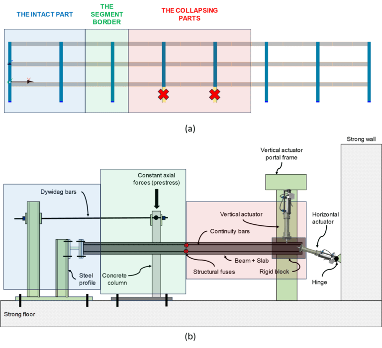
In the coming months, we plan to perform scaled-down subassembly tests representing a part of a complete structural system (Figure 2a). Four specimens will be tested in total: two for the cast-in-place RC subassemblies and other two for the steel/composite framed structures. The subassemblies are selected and designed carefully to allow a thorough observation of the structural behaviour before and after the fuse activation. Each subassembly will comprise three main parts (Figure 2b): 1) the collapsing part where the collapse front is propagating from; 2) the intact part that represents the part of the building that is being protected from the collapse; 3) the segment border that represents the junction (intersection) between the collapsing and the intact part. In the collapsing part, two hydraulic actuators will be used: the vertical one will impose vertical displacement, and the horizontal one will introduce the pulling forces adjusted to the magnitude of collapse forces from the structural system’s analysis. The segment border is designed to prevent the collapse from propagating beyond. Lastly, the intact part is designed to mimic the behaviour of the remaining parts of the structure and provides some degree of restraint.
These tests will be part of the Endure project research, which has received funding from the European Research Council (ERC) under the European Union’s Horizon 2020 research and innovation programme (grant agreement no. 1101000396).

Figure 1. (a) Schematic of the structural fuse implementation; (b) experimental test setup to perform the structural fuse characterisation; (c) failure mode observed in some preliminary tests.

Figure 2. (a) Hypothetical scaled-down building to be studied; (b) adopted test setup to perform the subassembly tests.
